What's New
- Just enough or OK in all circumstances? On cables and inverters
A simple question in a camper forum brought some surprising new knowledge for me. The situation was simple: Somebody had a 2500w inverter and wanted to know what cable size would be needed for that kind of power. Now, the most popular formula is "ampere needed divided by 3 gives the mm2 of the cable". It shows up in the victron paper "wired unlimited" mentioned below.
There is also the "world formula" by tigerexped and it goes like this: mm2 = (2*length_of_cable * Ampere) / (58 * 0.1)
. 0.1 is the maximum loss in voltage allowed. Remember that high ampere values turn even very small voltage losses into a veritable heater...The result is around 70mm2. But how did we find the ampere needed? Dividing the 2500w by 12v gives 208a which is well within the cable size of 70mm2. Well, is it really? If we assume 12v we could make the first mistake: regular lead/agm/gel batteries can go down do 10.5v and in that case the current output gets much higher to balance the loss in volt. In this case the user had a lifep4 battery with a bms that should protect the battery and prevent it from going too low. Btw: a decent inverter nowadays should have 2 important features: a slow start when turned on to avoid sparks in the switches AND support for modern batteries. Which means it should be configurable with respect to the low-voltage-turn-off parameter.
OK, we could skip adding more ampere due to the battery type but there is another thing we cannot skip: If the inverter really can deliver 2500w we need to add the current needed by the inverter itself to perform. The so called ETA and it can be between 10 and 15 percent of the expected output. Ooops, that could easily bring us up to 230a and now our wire of 70mm2 is no longer enough. Now 95mm2 looks promising seemingy in any case. But is it really enough?
The problem lies in the fact that both formulas do not consider the temperature in which the cable has to perform. Take a look at the Current-by-temperature table. It shows that we are fine with as 95mm2 at 30 degrees but at 50 degrees we are below specification with respect to the abilty of our cable to carry the load.
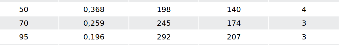 But is 50 degrees celsius not a bit much to assume? Not in a camping context. Some camper specialists even assume 65 degrees in the worst case when the installation is within an enclosure with poor venting.
 Do we really need to go even higher with the cable diameter? I can tell you a little trick here: What about two 50mm2 cables in parallel instead of one big cable? The table shows that two cables counted together have a much higher heat tolerance than a single larger cable. The surface is simply bigger in the case of two cables and allows better heat dissipation. If we want to be correct, it does not even end with just temperature affecting our cable. The table below the temperature shows how the installation style also affects performance. In our case with just four cables and enough room to space them properly we can assume a loss of only 10percent and with 252a we are still fine.
But the fun is not over yet. While we arrived at a cable size way beyond what had been installed originally we have another question to answer: how big a circuit breaker do we need? The circuit breaker protects the cable! Not the device. That is why we have started with the needs of the device and derived the proper cable size given the usage context. When the current exceeds a certain value the breaker (typically of the melting type) needs to separate the connection.
It helps to take a look a the following paper by tigerexped on how to select the proper breaker.The following diagrams are excerpts from that paper. Every breaker has a rating and its behavior changes with respect to the percentage of current that exceeds the rating. This allows more current to flow for a short period of time. This helps e.g. to overcome start problems when a device needs more current only for startup. So how do we select the proper norm-value of the breaker? The value certainly has to be higher then the ampere needed by the device. Otherwise the device will not work. The value also needs to be at the high end of the cable capacity otherwise we do not make proper use of the cable. It needs to be small enough so that it can be triggered by the current applied. Otherwise the breaker is useless. The maximum current is usually given by the battery and its BMS. And there is a difference between breakers below and above 125A: the bigger breakers only allow 75% of the norm-value to be used continuously. And last but not least: also the breakers suffer from degradation by higher temperatures and need to be adjusted.
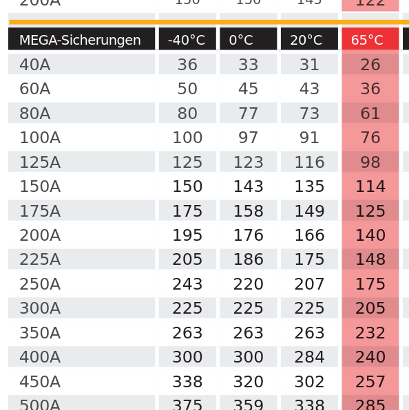 .
. Our device requires max. 230A, our cables allow for 280A at 50 degrees and if we can avoid running continuously at extreme temperatures and max. load we can get by with a 300A breaker.
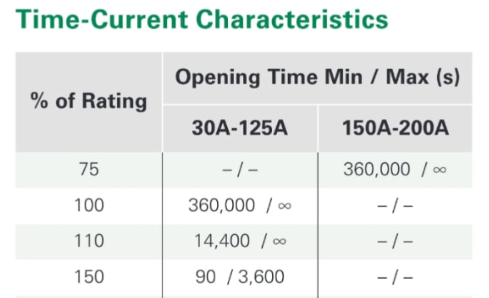
Ok, we are almost there. We have learned that the inital formulas did not consider environmental temperature or time. But inverters offer an additional time related problem: The allow for a massive overload of more than 100% overload for a very short period of time. This supports the startup behavior of engines e.g. This is another case where we need to rely on tables - here the breaker tables - to select a circuit breaker slow enough to allow for the overload.
To end this post, let us go back to the title and the question of "just enough or works in all cirmumstances". The owner of the camper in question reported high cable temperatures and inverter shut-off around 1200w. As the inverter itself supports up to 2500w, my guess is that an undercurrent situation was detected. It could also have been the BMS of the 100Ah battery. But it had worked in the past! Well, in that case the previous owner probably did not exceed some lower current level with her devices and no shut-off happened. With larger devices it did not work any longer, even though the inverter was large enough. The case shows nicely what is wrong with "just enough" in electrical systems. User behvior changes and suddenly there is a problem. And the problem may even be hidden for a longer time: The new owner took the camper to a repair shop where they detected, that the 10mm2 cables had already baked together due to the extreme heat in the cabling. A fire waiting to happen. The newly installed cables were of 70mm2 size. The undersized battery was not changed which might create problems in the future when devices are changed.
- Modern Batteries - a Security Nightmare? Part 4(final)
In the third part of this series I mentioned the Round Display Extensions and the possibility of using an SD-card for storage. I used this feature to allow setting the mac address and keys without patching the source code
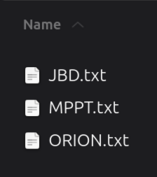

The files (JBD.txt, MPPT.txt and ORION.txt) need to be present on the SD-card. The first line is the mac address (something like 97:a4:c5:88:b2:23 ) and the second line needs to contain the 32 digits long key from within the Victron app for the respective device. All lines need to be properly terminated by CR and/or LF (if you use cut and paste hit return at the end of the line).
The code will first check if the source code was patched directly. If this is not the case it will try to read the files on the sd-card.
I discarded the option of letting the user enter the values through the GUI as this is a very tedious process in case of the security keys. Please note: the key entry for the JBD.txt file needs to be set too even though it is only a dummy.
- Some Ideas for Thesis or Project Work
-
All things medical usually come with a huge price tag. This is a major problem for patients which would require daily workouts to improve their situation. Alas, the cost of equipment restrict training to few ours a week. I do have a friend who suffered years ago from a major stroke. He is still making progress but his access to high-tech exo-skelettons etc. is limited. Much of the regeneration of brain features is based on the mirror principle: if the patient sees the problematic hand really moving, cells in the brain get regenerated. Could we achive something along those lines with VR glasses and game controllers? The equipment ist very affordable. The patient would need to see his hands in VR and the game controller steering wheel allows the good hand to tag the other hand along - mirroring the pictures in VR.


The next idea is the result of a chirurgical intervention lately: I had problems with a tooth. The dentist turned out to be very interested in all things IT and told me about his dream: documenting the interventions is always a very time consuming process. Could so called AI glasses help to reduce this effort?
 I am sure the glasses would have even more uses at a dentist. The project or thesis would have to find those and perhaps come up with a prototype - in tight connection with the dentist and the dental organization. There is one very important requirement besides documenting the process: the data cannot leave the premisis of the dental clinic for privacy reasons. The dentist said that they could not accept e.g. storage in facebook as is done currently by the Ray Ban glasses. Talk to me if you are interested in either one of those ideas.
 - Modern Batteries - a Security Nightmare? Part3
-
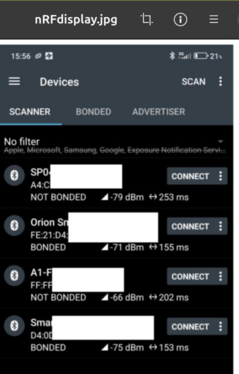
In this third installment I will explain how to adjust the software for the arduino and how to get the keys from the victron device. The keys are needed to decrypt the victron advertisements. But the first question is: are you affected? If you use the Nordic connect app it might display something like the image nearby. Watch for those entries which are "not bonded". You see both Victron devices as being reported "bonded". This means that they have exchanged key material with the Victron app and - if properly implemented - should be safe. What about the "not bonded" entries? If those devices do not have an additional physical means (like a button) to establish (and secure) bonding to an app, they are open for any app to connect to.
I have talked about the overkill app being able to remove an existing bonding. You will have to decide whether to test this with your battery at your own risk. In the worst case your fake password protection will be removed and you end up being in the "not bonded camp".
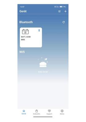
Lets say you found your battery being "not bonded" and the BMS is a JBD type. You will have to adjust the mac-address of the battery in the source code. Your ecoworthy app will show the mac address in the withe box. Now if you look at the nRF image you will see, that the address is also shown for every device (it looks like a1:06:e3:78:12:b3). And the same goes for the Victron devices.But due to their encryption you will need the established key between the Victron app and the Victron device. Luckily the Victron app can expose those keys (see image) and you will need to patch the source code with those keys. One last ugly piece is left: I have hardcoded the number of temperature sensors in the code. If you have more than three you will need to adjust the value. That should be all to get the arduino with the round display going.
 And a final piece of advice regarding the values shown by your BMS: Your BMS is lying! It might report a SoC (State of Charge) of 90% but suddenly there is no energy in the battery. If you look closely you will notice, that while the SoC is still high, the voltage level has dropped below 12Vand the BMS has shut off the battery to protect it. What happened? Many BMS can deliver hundreds of amperes but they tend to miss very small consumers. Gas sniffers, some small LEDs will not be detected and therefore not substracted from the SoC. Always watch the voltage levels reported!!
After writing the first paragraphs I noticed that there is a way to let users configure the devices by themselves: The round display has a slot for a micro SD card. See: Round Display Extensions on how to use it. And the BLE scan discovers the Mac addresses of the devices anyway. A little piece of GUI code could present the collected Mac addresses and let the user define which belongs to the BMS or the Victron devices. At the end the relations are stored in a file on the SD card. The GUI needs to allow removing the file too. In the end all users have to do is to download the arduino ide and the software and click on "upload". The rest is GUI configuration.
- Modern Batteries - a Security Nightmare? Part2
-
In the first part I've explained the problem of unsafe BMS (Battery Management System) i.e. BMS that do no support bonding through the exchange of key material (e.g. a password) and also not provide physical means to prevent unwanted connections from outside. Carsten, a member of the ducatoform told me about his solution using a esp32c3 with BLE (Bluetooth Low Energy support) and Wifi to run a permanant connection to the battery - thus preventing unwanted connections from others. His c++ sourcecode gave me starting point. even though my battery used a different BMS.
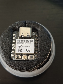
An esp32c3 from Seed Studio has roughly the size of your thumbnail. It comes with all kinds of industrial bus interfaces and has very low power requirements. It attaches direktly through a USB cable to your PC and supports debugging. The next steps were: :
- Downloading the Arduino IDE and the supporting Library from Seed Studio. - Installing the IDE and getting it ready to connect. - trying to remember things about c++ and learning some things on BLE. - Finding information on the BMS, in my case it is a JBD BMS. Especially the protocol info is necessary to request battery information and parse it properly. This means understanding advertisements received and callbacks from requests. - finding a way to attach a display to the controller and learn how to program it - Finally finding a case and mounting everything inside the camper (a complete mobile solution is also possible) I have never done anything with Arduinos and my last fight with c++ was roughly 30 years back when me and my team built one of the first frameworks using this language. But with the help of Seed Studio getting started I had the IDE up and running in nothing. (I am using Ubuntu btw; haven't done a thing with Windows in ages). Once I found the right tty the connection to the board worked immediately. Getting into the IDE took me a while but in the end all IDEs work somehow similiarly. The good old c++ practice was back: always look into the source code of those components calling you and those you are going to call to see what is happening with the pointers. Std::string (can a lange be more ugly???) not working properly was another bummer. But over time I got familiar with c++ again and for the most part I did copy/paste/adjust anyway.
How can I talk to my BMS? Luckily some sites had a rather complete description ofservice requests and responses and from other programs I took some checksum routines as well.
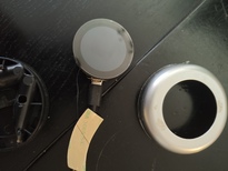
Now came the display.I have never been a front-end person in my whole life. So this was quite a challenge for me. I decided to go with Getting Started with Seeed Studio Round Display for XIAOas I did not want a large panel. The beauty of this 1.8 inch round display is its perfect compatibility with the esp32c3 from Seed. It just lets you plug the controller into the back of the display
Next came BLE and as I was going to use the NimBLE library for Arduino I took a closer look at the examples that come with the library. I noticed that most code used variations from those examples. Now C++ was a different issue. After endless years of using languages with a garbage collector it was like being transported back in time 30 years: Oh, I am getting a pointer on an advertisement in a callback? Can I hold on to it? Who is going to delete it? and When???
 .
.

 To program the display I used the rather simple TFTesp library.
Well, in the end I got a little bit carried away and tried lots of different things like extended advertisements (lets you transmit larger data sizes in advertisement e.g like beacons. No connection needed. And I found a little piece of clock codethat uses the RTC clock on the display (you need a cr927 battery). And I used the touch feature of the display to create a menu for setting the clock, starting and stopping monitoring (you will need to stop monitoring the bms if you want to use the regular app, otherwise it can't connect) and showing system state or debug.
I have not found the proper place to mount the device in the camper. I am also still thinking about the usb c powersupply needed. It does not need a lot of power but it needs a switch. One option is to keep the whole thing mobile and not mount it at all. It all depends on the new inverter I am planning to install because that would let me use 230V usb chargers.
- Paolo Cognetti , Le Otto MontagnePaolo Cognetti , Le Otto Montagne
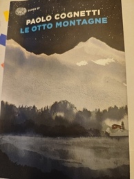 Se volete imparare il passato remote nella lingua italiana - questo libro è per voi. Tutto è raccolto nel passato remoto. C'è anche un film sul libro ma non era un grande successo al cinema. Il libro non mi è piacuto molto. È un po triste e a volte noioso con poche sorprese. D'altra parte le descrizione della vita in montagne- la poverta, il tourismo, il cambiamento climatico - e fascinante. Il tourismo ha portato piu soldi nelle montagne da dicenne. Ma come si diventerà la futura nei villaggi degli Alpi senza neve? Quando i touristi non vengono piu? Il libro e facile da leggere anche per non-madrelingua.
 - Saverio Lodato, Quindici anni di mafia
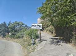
 Ho comprato questo libro usato nella bellissima antica Libreria in via Vittorio Emanuele a Palermo. Prima sono stato a Corleone, la città dei "corleonesi", la più brutale famiglia tra le famiglie mafiose in Sicilia. Hanno ucciso entrambi: Falcone e Borsellino e molti altri giudici e poliziotti. Il libro - scritto da un giornalista del Corriere della Sera - spiega da dove viene la mafia, come si è cambiata (principalmente a causa dell'eroina) e come lo stato ha vinto la guerra (la legge La Torre e i pentiti). E no, non è mai stata la mafia un'organizzazione per la gente. Nessuna ragione per romantizzare la Cosa Nostra. Il libro non è stato facile da leggere per me, comunque molto interessante. E oggi? Che cosa fa la mafia oggi? Penso che sia cambiata un'altra volta. Oggi fa principalmente affari e politica. E ci riesce con grande successo.
- Sbagliando s'impari
 Well, I guess with this book from the Feltrinelli bookstore in Palermo I have bitten off a bit more than I could easily swallow. It is rather hardcore italian language diving into the deepest questions in syntax, morphology and many other areas. It took me a lot of time to get even half through the book and the texts used for detailed analysis often come from famous italian writers of the past -making it extra hard to understand the problem. It has become a bit of a long term project and and slowly I seem to get an even deeper understanding of grammar - a topic that I have always despised previously. I admit that I even watch youtube videos on grammar for example from Raff or Podcast Italiana.
 - Sean M. Carroll, Something Deeply Hidden in the Quantum World?

In the past I enjoyed several talks on quantum computing. And once even did a journal club on Shor's al gorithm: a quantum algorithm for finding the prime factors of an integer. Which in turn allows current public key encryption to be cracked. That's why we are implementing so called quantum safe algorithms today, expecting quantum computers to become more powerful. The talks were really fascinating to listen to but in the end I left every time feeling both well entertained and clueless as before. And the journal club left me kind of speechless about the transformation of an algorithmic problem into something that might be solved on a quantum computer. And what entanglement and superposition had to do with it totally escaped me. It looked like a colleague from IBM once told me: "I just hope to reach retirment without having to understand that stuff.
Then my colleague Roland Schmitz started a lecture on quantum computing and security and Nadine, his assistant sent me her master thesis on how to teach quantum computing. And that got me interested again.
Well, after taking a look again at complex numbers etc. I still felt absolutely clueless about the topic. Bruce Schneier even mentioned in this cryptogram newsletter a paper on quantum computing that made the whole thing look like a fake. The paper mentioned that not one complex problem had been solved yet by quantum computing (not that I claim to really understand the argument made). Time for some basics and the book from Carroll had been sitting on my desk for quite a while already.
What did I learn? Well, the first chapters told me that today few physicists are really interested in how "real" quantum theory actually is. Being able to do useful calculations seems enough. Einstein was not satisfied with this and insisted on a better connection of the theory with how the classic world looks to us. I learned that initially people thought that the fundamental concept of everything being probabilistic "deep down" was just a sign for the theory being incomplete. Later people - especially the representatives of a "many worlds" approach seemed to settle on the wave function of the universe being the single reality and the classic world being only a result of our measurements. Measurements make the wave function collapse and our classic reality appears. Except that some believe that the wave function does not collapse but simply branches into different worlds.
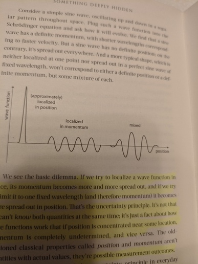
I also learned that my understanding of the Heisenberg uncertainty principle was totally wrong. The chapter on "what cannot be known because it does not exist " is one of my favorites in the book, besides the following one on entanglement. I understan now that the classic measurements of position and velocity (momentum) cannot be repeated in quantum space because both do not exist at the same time: The "particle" is an amplitude in the quantum field and at that moment does not have momentum: the field is gone. When we measure the field (wave), there is momentum but the particle is smeared all over the wave and hence without position. Then came entanglement - the fact that when one of two entangled quantum things is measured, we will find the same measurement outcome on the other - once we measure it. Sounds somewhat fishy in the beginning but theorems like "no signaling" exclude larger than the speed of light communication here. But fishy enough to make some physicists believe that "some element of reality" - when both things were entangled - would play a role here. But alas, the famous Bell proof excluded this. Bell showed that these "elements of reality" could not predict the behavior of a second quantum thing when the measurements get closer to how the first one was measured. Quantum theory predicts a much higher outcome for the direction closer to the measurement of the first part. Something that the "element of reality" camp cannot achieve.
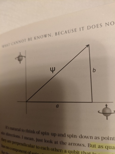
Going along I got a bit of an understanding why the probability of finding a particle is expressed as the square of the amplitude of the wave function.Usually the spin is considered orthogonal for measurements. But drawn as a triangle with a 90 degree angle both sides squared represent the probability of each outcome - together forming the 3rd line of the triangle (good old Pythagoras).
 And I got a better understanding of the importance of fields and that "particles" can be seen as vibrations in fields
When did Carroll loose me? I guess when he went into the depth of the "many wolds" theory and then took the whole thing into spaceThere were still interesting bits but the whole went over my head. So I decided to buy another book with the title "why nobody understands quantum theory - but everybody should understand it". But this will be for another time... .
In the end I got a better understanding of the basic concepts but I am still far away from having an idea how entanglement and superposition would work in the context of the so called "gates" (e.g. hadamar gates) in quantum computing.
- Modern Batteries - a Security Nightmare? Part1
Note
Before we dive into the security problems I need to clarify one point: I decided to buy a bluetooth enabled battery because I did not want to install an extra shunt for measuring charge and discharge. This was a misunderstanding on my part: the BMS is NOT able to measure small amounts of discharge. Over a longer time (e.g. when in winter storage) the values shown by the BMS will be WRONG and suddenly the battery will shut down or consumers will no longer work. If you REALLY want to know the state of your battery exactly, install a shunt, e.g. the one from Victron which is supposed to measure even small discharges accurately.
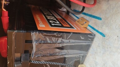
Now really, how could that happen to me? I mean after many years in IT-Sec. After so many bad news on failing security in IoT, smart homes, cars etc. I I decided to upgrade the electrical support in our vintage camper. I went and bought several Victron devices and compressor fridges. And after lots of youtube clips I fell in love with an Eco-Worthy 280Ah LifePo4 battery at a very good price. There are some clips that show how this battery gets disassembled and from what you can see it is absolutely well built. No complaints here. And I got myself the bluetooth version with protection for cold temperatures. I did not want to install a shunt to measure power consumption. And all the other devices support BT as well. What could go wrong?
 Well, after 3 tedious weeks of installing all this stuff in practically zero space I started to use the apps for the devices. The Victron devices all had proper bluetooth keys attached which had to be installed in the apps. The fridge also had an app and during installation a button at the fridge had to be pressed. And the app for the battery worked out of the box and showed important parameters of the battery - nice. We went on a long vacation and everything worked perfectly. No land line needed. Coming back I read a posting in ducatoforum.de which discussed a new app for my type of BMS which allowed finetuning of all parameters, backup etc. And it also was able to remove bluetooth passwords during that process.
 I guess this was the moment when I finally realized that my wonderful battery really was not protected at all and that basically everybody walking by with one of those apps (nicely called "overkill" btw.) could turn off the battery or even worse: install parameters that would permanently damage the battery. And the fact that even BMS with password protection seemed to be just as vulnerable. Remember: a BT enabled BMS will permanently advertise its existence to everybody nearby and the fact that it uses Bluetooth low energy in this case is not really an improvement. How could I completely forget about security when I bought all this equipment? Me, after all??? The typical excuses are: I looked only at the features and the price. I got lost in technical features. And so on.
OK, what now? I did a 5 min. risk analysis and came up with some rather ugly facts: Difficulty of an attack: low. Availability of necessary tools: easy/free. Risk for the attacker: low. Damage potential: high. Why high? Loosing the content of the fridge is a pain in the butt but not dangerous. Loosing the battery due to a bad configuration is really bad on vacation. But shutting off the battery while the heating system is running can cause a fire because the cooling fans usually need to run for a while after the heater is turned off. (This is btw. a sore point in all digitally controlled batteries. A solution would require connecting everything to a central battery controller ). Motivation for an attack: fun, vandalism, hate for campers. Who is at risk? Basically everybody using such batteries in homes (4 can be stacked and by doing so you have a veritable power bank in your home and perhaps a real fire hazard in case of vandalism) or vehicles. BLE's reach does not go that far but it can be far enough.
At that time I had no knowledge whatsoever about BT or BLE but it was clear to me that my installation had a serious flaw in the battery. I tried to contact the vendor but did not receive a response. Then I found a little hint in a discussion about the overkill app and its threat for batteries. Somebody claimed that while the BMS is connected to some app, it does no further advertising and does not accept new connections. I downloaded the nordicsemi nRF connect app and also the overkill app and did some tests. Yes, when the original Eco-worthy app was connected, the battery was invisible to others and also did not accept any connect requests. That left me with three options to choose from:
- Put my mobile phone running the original app permanently next to the battery. Not really an option and the behavior of the app was also unclear. - Buy a BMS monitor device on AliExpress. Cheap, with a display, but completely unknown behavior with respect to connection time etc. - Build some custom solution for my BMS. This is where I got lucky because a member of the forum had done exactly that - only for a different BMS. I even got his source code to start with and I am going to describe the solution in another posting. But before closing this post let me briefly discuss the solution. It is obviously not a real solution but a fix, a workaround based on "security by obscurity". Why? A real solution would require the exchange of key material to "bond" client and server of a BLE connection. Or use at least a physical thing like a button on the battery which is only accessible from inside the house or the camper. A hard-nosed attacker would try to use a jammer to interrupt the connection and then try to establish himself as client. But BLE has some interesting connect options which allow a rather long connection time without an interaction. But again, the "solution" of a permanent connection is just a workaround to prevent simple vandalism - which is the most likely attack. A final note: using the overkill app one can create complete backups of all battery parameters and this would allow to re-establish the original settings after a successful attack.
Note
Even if your BMS offers password protection, running a permanent connection might still be safer. If it is true that the overkill app can simply remove passwords. Unfortunately it looks like running overkill might permanently ruin the password feature so test it at your own risk. My code currently does not support passwords (because my BMS does not use any) but I guess this feature could be added without problems.
On a closing note: BT offers several ways to secure a connection between client and server. The problem is simply that vendors do not use them. You can read more here: Taking over a wheelchair through Bluetooth
- Modern Motor Homes - Scale changes everything!
-
Modern lifepo4 batteries are a game changer for camping vehicles due to their ability to store much more energy than classic AGM or GEL batteries. There is a lot of discussion about the proper way to install the new type of batteries: going from "just swap" to "rebuild the electric wiring completely". The "just swap" position is probably right as long as the ampere hours of the new battery are not too far away from the old one. E.g. swapping a 90Ah AGM for a 100AH lifepo should be OK - as long as the size (esp. the height), the mounting and the type of generator in the motor fit (problem "intelligent generator). Swapping with a new 300Ah lifepo4 will probably require more work. First, the new battery - especially when close to being empty - can charge at a huge rate. This might damage the generator or could cause problems when the cabling is to thin. Second: such a huge battery needs a lot of solar power to charge and this will probably require new chargers, cabling etc. And that means you are suddenly going from a rather simple architecture with one main switch
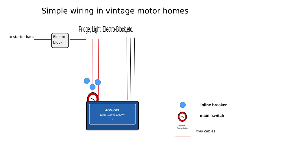 to something with many generators and with the positive and negative bus-bar in the center. Scale changes everything. This has nothing to do with your plans. It is simply the result of choosing a huge battery. If you stick with a small new lifepo4, chances are that you don't have to change a lot. But you also won't gain a lot from the swap. That means before you start thinking about technicalities you should define your goals: what do you want to achieve by swapping in new and powerful batteries? Are you simply going for an increased time away from regular camp sites and their land lines? A bigger battery and more solar panels and a new solar controller might already be enough. Or do you want to run a 230v air condition unit full time? Or do you want to swap out your gas range and install an induction range running on a high power inverter that also drives some other 230V sockets? Or are you going to be an autonomous van lifer living in a gas free camper? Your cable gauges and wiring will certainly change with your requirements. But whatever your final goals are. The basic architecture will probably derive from this one:
  At the center of your "star" are the bus bars, connecting several different generators with consumers. Do not forget the switches! see: DIN VDE 0100-721.They are sometimes required by the VDE for campers and they come in extremely handy in case of low temperatures (you might want to stop charging the lifepo4s when the temperature gets below zero) and maintenance (e.g. of the solar panels etc.). There is no longer a "main switch" and that means that you will have to think about the order in which you turn of generators. It is a bad idea to turn off the battery switch but leave the MPPT solar controller running. This will cause a floating level of power in your system and might damage consumers. If you spend a long time at a camp site attached to the landline: some chargers can provide regular 12.x DC for all the consumers. In that case turn off the battery and the other generators/inverters and live off the land line.
 I guess it is good advice to turn off all consumers before turning of the generators. At CMT Stuttgart 2025 a vendor told me that he turned off his battery while the heater was running. He was barely able to prevent a major fire as a lot of black smoke was coming from the heater: without electricity there is no vent to cool the heater - which gets extremely hot during operation.
A few words on special topics. The so called electro-block (EBL) contains a switch that is driven by the so called D+ signal from the engine generator when the engine is running. Only then will the EBL connect engine and camper battery to allow charging of the camper battery when the driving. But most people will install a so called booster for this purpose, to either protect the engine generator or wiring from overheating (chose the new configurable ones from Victron, they don't get so hot) or because their intelligent engine generator would otherwise not recharge the camper battery properly (newer vehicles only). The switch in the EBL needs to be disabled and a new pair of wires needs to be run between engine and camper battery for the booster.
Another topic that causes a lot of confusion is the use of an inverter or a power station. If you plan to install one, now is the time to read: PERSONENSCHUTZ IM IT- UND TN-NETZ and Fachbeitrag: Elektrische Sicherheit für mobile Stromerzeuger. As long as you do not require more than one socket behind the inverter, everything is quite easy: you are running an IT-network without a need for an RCD (FI) or ground wire. The reason is simply that your L and N wires are not connected to the ground. But with more sockets you need at least one RCD (if you convert your IT net to a NT net (like in most houses) or one RCD per socket if you stick to the IT net. In both cases you will need a ground/earth wire connecting all the sockets and the inverter. The conversion to an NT net is usually performed by splitting the N wire and using one part as an earth wire going to all sockets. The RCD comes then after the split. If the L wire touches the case of a device that is plugged in, the power will flow from there through the earth wire - bypassing the RCD which notices the missing power and shuts the L wire off. BUT: once the landline gets plugged in, the RCD that protects the landline will immediately notice that N and earth are connected and will turn off power. That means that there needs to be a relay that connects N and earth in case there is no land line and disconnects both wires when there is a land line. The land line gets priority (in german: "Netzvorrangschaltung"). The good news is that recent inverters for motor homes already include those features. Just follow the manual. If you think: what the heck, I don't need that crap. It's only 12V that drive the inverter - think again. 12V * 200Amps is 2400W. 2400W / 230V is a whopping 10 Amps!! Scale changes everything!
OK, one last word of caution: many cheap inverters from China have two sockets. In most cases you have no knowledge about the circuits inside. You can't even assume that the inverter has complete galvanic isolation (e.g. through a transformer). Some want an extra connection to the ground, some don't. You can only hope and assume as litte as possible. For now I'v decided to use just one socket.
For many people the correct selection of a MPPT controller (solar controller) is a problem. How many volts, ampere and watts are needed? Well, that clearly depends on how powerful your solar panels are AND the way you want to connect them. Please take a look at the Victron book below for some possible ways to do so. The book also explains the dependency between volts and ampere in you installation: a serial connection drives up the volts, a parallel the amperes. A parallel installation is better when there is a frequent chance for partial shadows on your panels because if one panel is in the shade, the other can still deliver power. BUT: your cables need to support the amperes!! the book will tell you how to calculate cables but it does not tell you a little trick: if you go for high voltage panels (e.g 36V and up) and connect them in parallel, your amperes will go up but not as much as with 12v panels. I have chosen the Victron 100/30 which would support 100V and delivers 30A to the battery. It supports 440W at that is exactly the power from my modules. The amperes from panels to the controller are roughly 10A and that still fits my cabling nicely. With low-voltage panels I would have had to upgrade my wiring.
Now it is time to get down and dirty with the installation. I urge you to read the book "Wiring unlimited" by Margreet Leeftink
 first. There is also a german edition available. It will tell you all about cable sizes, connections, tools etc. The higher you go with the amperes, the more critical becomes the wiring. For the really big motor homes the only reasonable choice is anyway to go to a 24V or 48V installation to reduce the danger. But stretching 12V systems to support 3000W inverters is a risky business. 3000/12V means 250A will flow through the wires. A rule of thumb (the book has more detailed formulas) says, that for short distances you can divide the amperes by 3 to get the mm2 needed. In this case we are around 85mm2 for the copper wires to the inverter. Assuming a distance no longer than 1 or 2m between battery and inverter. Keep distances as short as possible. In extreme cases the position of consumers and generators on a bus bar should be taken into account and kept as close together as possible. One last scare: lets assume 2m of copper cable 70mm2 and 250A. The resitance is 0,017 * 2 / 70 == 0.00048Ohm. The formula to calculate the power loss is P = Ohm * ampare squared. In this case we experience a loss of 30W just within the cable. Now imagine a bad connection at the bus-bar or at the inverter resulting in an extra 0,001 Ohm. The loss is now 0,00148Ohm and multiplicated with 250A squared we get 92.85W!! This is called a fire hazard! If you plan to build a gas-free camper with induction range etc. I would recommend at least a 24v installation.
The loss in voltage due to the cable results in an increase in amperage needed to run a device and causes extra heat being created. You can specify how much voltage loss is acceptable for you and use the so called "world formula" from the company tigerexped. It will tell you how many mm2 you will need to achieve a certain voltage loss and not more. BUT - and there is a big BUT here - do not assume that the formula will tell you what cable size you can REALLY use. It will only tell you the size that allows a certain loss only. This does not mean that the cable size can really carry the intended load. You absolutely have to take a look at two important diagrams (attached in the link from above) on how temperature and the way the calbles are routed affect the maximum load the can carry! Especially with very short wires between e.g. a battery and an inverter, the world formula becomes very sensitive to the voltage loss parameter and underestimates the cable size needed. An example: a 10mm2 cable of 30cm may be acceptable for a 1000W inverter at the first glance. But a look at the temparature table tells you that a 35mm2 cable is much more appropriate for constant use of the inverter (I will discuss this case in more detail in a later post). And if you look at the tigerexped paper don't forget to also take a look a their paper on how to chose a circuit breaker and how they work. Also here temperature plays a major role and might require a much larger breaker than initially planned. The electrical compartments of campers can get quite hot in the south of Italy e.g.
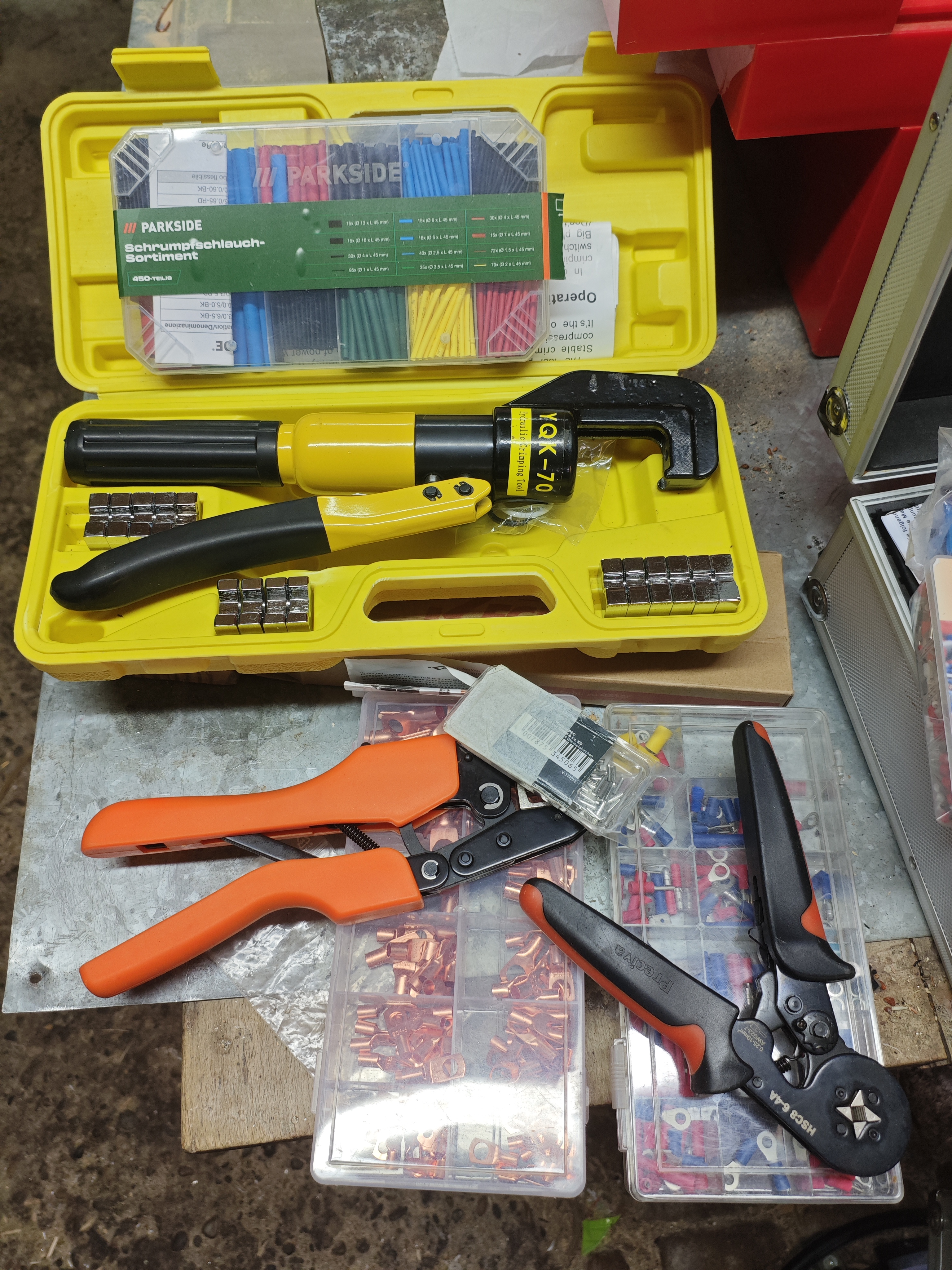
A few words about the installation cost. You need decent crimping and measurement tools (hydraulic, with pliers etc.) and you should ABSOLUTELY not try to save money on the installation material. For the reasons given above. You should calculate for materials like cables etc. at least 500 Euro. And when you buy bus bars etc.: Go an measure the cross section! you will find stuff that says 250 amps on the package but comes with a very thin metal plate - often not even using copper.
 A very good source on wires and tools is Klauke Fachwissen: Verbindungstechnik und Pressformen. It shows all kinds of bad crimping and the reasons for them. I wish I had known it before rebuilding my wiring as I was fighting with overpressing (getting ears on the crimped object) due to cheap material. One thing that I do not yet understand is the performance of cables made of different amounts of single wire like in this picture from the Klauke paper. The Victron paper explicitly discourages the use of class 2-5 wire which sounds reasonable because with fewer wires the overall cross section becomes smaller due to the larger radius of the wires within the cable. But it stays unclear how big the loss in performance across the classes really is. The formula for performance loss in cables do not include this loss.
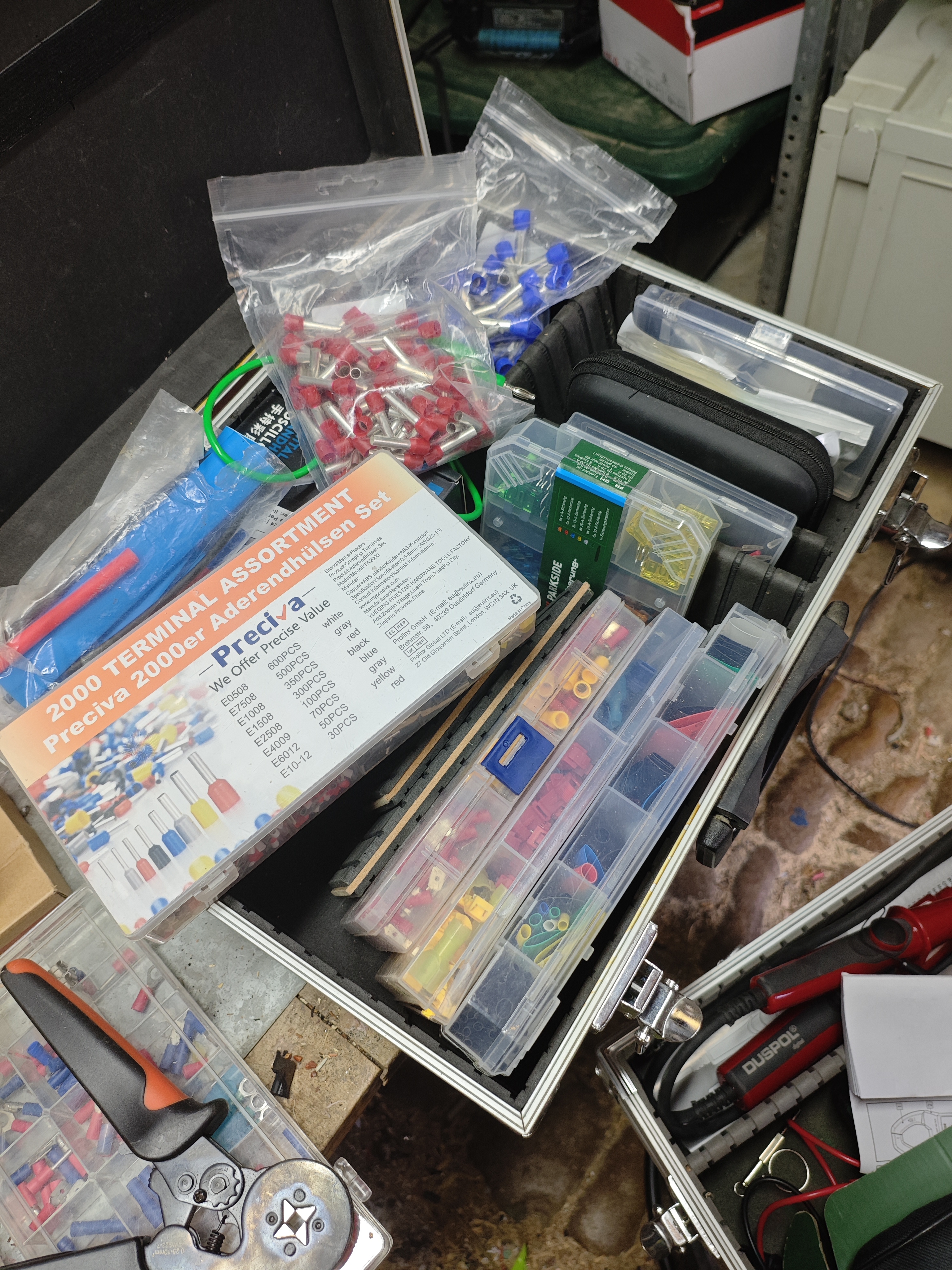 Forget your old crimping tool used to connect some wires on your car radio. It will not do. And watch out for the wiring sizes supported on your devices! Most smaller victron devices support max. 16mm2 cables!
Saverio Lodato, Quindici anni di mafia
Sbagliando s'impari. Esercizi per mettere alla prova il proprio italiano
Something Deeply Hidden: Quantum Worlds and the Emergence of Spacetime
Paolo Cognetti , Le Otto Montagne
Judea Pearl, The Book of Why 
Frederic Laloux, Reinventing Organizations 
Rutger Bregman, Utopia for Realists 
Yuval Noah Harari, Homo Deus 
Jakob Augstein (Ed.), Reclaim Autonomy 
Judea Pearl,
Causality 2nd ed. 
The Art and Science of Cause and Effect, Judea Pearl
The Art and Science of Cause and Effect, Judea Pearl